
.png)
 By
By  Friday, January 31, 2014

Well here's where it becomes a little more complex, married to the turbo shaft we find a MGU-H (Motor Generator Unit - Heat) this is fancy terminology for an electrical motor. Furthermore attached to the crankshaft (via a gearing arrangement) we find a MGU-K (Motor Generator Unit - Kinetic) which is essentially a beefed up version of the KERS electric motor used by the teams in one form or another since 2009 (excluding 2010).
Several complexities arise when we establish that these 2 electrical motors can be utilised to recover energy and dispense it and even more so when we consider their power input/output relationship.

As always the manufacturers/teams/F1/FIA have been coy in explaining the usage of power and we tend only to see power figures etc displayed in a linear format. The problem with this is that we now have to see KERS as analog and ERS as digital, with the former providing ex BHP for a set time that the driver pressed a button or triggered a paddle on the steering wheel. ERS will be intrinsically linked and mapped to the position of the torque/throttle/accelerator pedal meaning that the way in which power is harnessed can be altered in a 3 dimensional context.
As you're now seeing the MGU-K's energy release as a 3D map you'll also realise that the time component of 33.33 seconds used above is junk and will likely result in much more energy available to the driver throughout a lap. Hopefully this will allay any fears you had about the drivers only having the 600bhp the ICE produces when not supplemented by the MGU-K.
As I've only covered the MGU-K thus far in the ERS lets have a look at the MGU-H which takes care of regulating the Turbo's speed.
One of the issues with turbocharged engines is lag, the bigger the turbo, the more lag you tend to get. Motorsport has been intrinsically involved in the development of technology surrounding turbochargers in the past, with VGT (Variable Geometry Turbo) and anti lag just a few methods employed to increase power or efficiency. These methods are not available to the engine manufacturers for the new power units but the MGU-H looks to profit from the motor generator unit in the same way (spooling up the turbo for instantaneous power).
Each of the manufacturers (Ferrari, Renault and Mercedes) will have undoubtedly taken different paths in terms of how to mount the MGUH to the Turbo but invariably that just takes into account how they want to utilise it and package it.
The MGU-Hs job is to essentially keep the turbo spooled up for instantaneous boost when the driver returns to the throttle.
As we can see from the energy flow diagram from above the MGUH is governed by several pathways. An unlimited amount of Energy can be recovered/stored whilst the same can be said for usage from the Energy Store (ES). The one constant however that dictates how and when the energy can be used is that ES cannot exceed 4MJ per lap.
The other option however is that energy passes directly between the MGU-H and MGU-K missing out the middle man (ES). Of course the best way to do this is when the driver is off throttle, recovering energy via the MGU-K under braking and out of the low traction phase pass this to the MGU-H to keep the Turbo spooled. On the flip side the MGUH will act like a mechanical wastegate, harvesting energy from the Turbo as the boost climbs at an adverse rate and feed it directly to the MGUK to facilitate more power.
This process will require intricate mapping by the team/manufacturers engineers as with the throttle closed and boost being created it could lead to "Surge". This is an undesired effect as it will undoubtedly shorten the lifespan of the component and increase the heat within the unit.

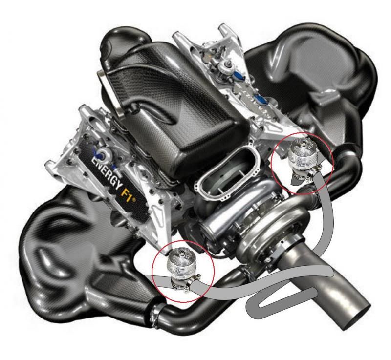
However how about if we utilise a wastegate? A wastegate is the manual method of bleeding off excess turbo pressure and is set to a prescribed pressure, at which point the wastgate opens and in the case of the 2014 (onward) engines would expel the unwanted boost out of the exhaust (again a precise and complex process due to the interaction of exhaust gases post turbo).
The Speculation part of the article: Will we see/hear Off Throttle Turbo Blowing - OTTB
Are wastegates even allowed? I refer you to the Renault Sport F1 page, as the manufacturer who has been most candid about their 2014 PU, they openly discuss the complexities of using a wastegate within the system. Due to the V'd ICE configuration and the way Renault talk about packaging it's safe to assume that an external wastegate will be the weapon of choice, however I'd also suggest this could become plural due to the way the gasses enter the Turbo.
Brilliant, haven't we chanced upon the newest form of exhaust blown diffuser (EBD)?
Not quite, EBD's used in the last rule set worked on the principle of sealing the Diffusers outer edges. As we know the exhaust exit has been specifically placed along the centreline of the car in a tip up format by the FIA to try and prevent EBDs being proliferated. Furthermore the height at which the exit must be placed is set at between 350 and 550mm from the reference plane meaning its interaction with the Diffuser's edge is made more torturous. Armed with this information we can see that it will be somewhat difficult to utilse off throttle blowing in the same manner but that's not to say it cannot be used in a different way....
The loss of the Beam Wing which resided between the rear wing in previous seasons in order to mount the wing to the crash structure, also created an aero structure which allowed the Diffuser and Rear Wing to interact (or talk to one another as such). With all three airflow structures working in unison the teams were able to maximise the level of downforce created whilst maintaining a lower level of drag.
.jpg)
Not wanting to lose this effect McLaren have taken the option of shaping their Wishbones into a profile that replicates the Beam Wing and have begun testing it in Jerez. However with the exhaust placed centrally McLaren and the rest of the teams will try to re-enact this airflow using the exhaust and the surrounding components.

However lets think about when these flow structures are required the most: Off Throttle. As the driver comes off the throttle and enters a corner he wants maximum downforce in order to attack the corner, if the teams/PU manufacturers found a way in order to keep the airflow interacting more downforce would become available. A plausible way of doing this is to use the MGU-K in order to slow the vehicle (harvesting) whilst sending the power directly to the MGU-H to keep the turbo spooled, as the pressure is raised in the TC by the faux spinning of the compressor by the MGU-H there needs to be a pressure relief as the throttle is closed and can't accept the rising boost levels. The Wastegate(s) cut in and dispatch of the the airflow out of the exhaust, placement and pipework to and from the wastegates would be essential not only because there is performance to be gained under normal operation of a wastegate in this manner, but by placing the wastegate exhausts on the pheriphery of the main exhaust in the right position you can also make the airflow move helically, energizing it's flow. I believe this may have been a reason why the FIA changed the regulations late on to stipulate a singular exhaust exit as it would have been much easier to gain an aero advantage from a smaller singular wastegate exhaust mounted correctly than what I've proposed here.
Like the off throttle blowing we saw in 2010/11 the drivers would have little to do in regard to controlling this effect as the systems at play would be complexly mapped before they even climb aboard.
During the last use of off throttle blowing we also talked about the use of cylinder deactivation by the teams to continue pumping airflow through the engine (for aerodynamic performance) and not only that but retain some throttle rather than the driver having to ease all the way off. Cylinder Deactivation will still play a large role in the V6 engines with an increase in fuel efficiency when at low throttle input, whilst the move by F1 to direct injection means the fuel injection stream is more precise and optimizes flame propagation. For those uninitiated in the phrase cylinder deactivation this is the practice of shutting down a number of cylinders in order that the remaining cylinders operate at peak efficiency, saving fuel and lessening the transition between full and open throttle. With fuel efficiency at such a premium due to the 100kg weight limit imposed for the race, the use of tactics like cylinder deactivation will become common place. If we also refer back to the insinuations I have made about gaining an aero advantage from the Turbo Wastegate(s), cylinder deactivation can also be used to manipulate this flow.
The whole scenario is fraught with complications owing to the complexity of all the systems at hand and so I look forward to seeing how all of this new technology is handled by the teams and PU manufacturers. Many have also complained in the past that these V6 engines will sound terrible when compared to the outgoing V8's, my retort has always been the same, "They will sound like nothing else, intrinsically Formula One" and with that I leave you with the following video taken at the first test in Jerez. Make your own mind up but personally I think they sound fantastic, an amalgamation of V6 exhaust, Turbo and electrical energy.


Fwd to the 45-second mark , turn up the volume and enjoy ...
ReplyDeletehttp://www.youtube.com/watch?feature=player_embedded&v=upNqwUvVnEg
I believe you wrote something about hot and cold exhaust blowing last season, after the insinuation of redbull using off throttle exhaust blowing. You stated then, correctly, that the actual throttle valve isn't closed at all to prevent the rear wheels from locking up.
ReplyDeleteFor upcoming season I don't believe they can close the throttle, because of the same effect. That would eleminate the need for a wastegate.
In road going petrol cars the wastegate is used the bleed of exhaust volume/pressure to limit the amount of boost pressure. In the new engine setup the MGU-H limits the boost pressure.
Then I got a question about fuel consumption. Is it measured over a whole hour? Meaning that the car can use 160kg/h for 20% (12min) of an hour as long as during the remaining 44 min it uses less then 90 kg/h. Or is the fuel cons. measured during every millisecond, limiting the fuel cons. at 100 kg/h during the whole race?
I believe the fuel consumption is measured at the end. That is 100kg consumed from 'Lights Out' to 'Chequered Flag'. The car actually starts with more than 100kgs to cover 'out lap', warm up lap' and 'return lap to Parc Ferme' at end of race. If the person wins but uses more than 100kg I don't know what the procedure is??
ReplyDeleteInstant death during the podium ceremony lol
DeleteNo, fuel consumption is measured in real time: ie it is an instantaneous measurement - The FIA paid big bucks for the unit to be designed and produced. They had problems with it not be accurate enough...it reads to around +/- 1%. So any usage beyond a RATE of 100KG/Hr should be a disqualification.
DeleteThe bottom line is also that a team can start with as much fuel as they like....during the race they can only consume 100KG's. Obviously if you were 100% power your fuel only last an hour. Matt might correct me but I think the biggest % of full power is around 70%. Of course it gets complicated as that doesn't necessarily mean that this is at a rate of 100KG/hr. That's what engineers are for!
I think I'm going to have to read this article many times during the early season just to remind myself what is available and achievable with these new power trains.
ReplyDeleteGreat article, thanks
ReplyDelete"Make your own mind up but personally I think they sound fantastic, an amalgamation of V6 exhaust, Turbo and electrical energy." < < < agreed! And it's gonna be even more amazing to hear the din from 20+ of these machines, launching off the grid and racing towards T1!!!
ReplyDeleteGiven the complexities of power delivery with the new system, how can they hope to police traction control?
ReplyDeleteTC is still prohibited and requires sensory input and reaction which unless the driver is also changing maps during poor traction moments his only control still remains the throttle pedal.
DeleteCould it be that you made a mistake her?
ReplyDelete"The one constant however that dictates how and when the energy can be used is that ES cannot exceed 4MJ per lap."
If I´m right they can recover more than 4 MJ per lap and release this. Only the release to the MGUK is capped at 4MJ per lap.
An the maximum storage capacity is 4MJ.
Yes ES = Energy Store, which cannot exceed 4MJ of storage per lap whether attained from the MGU-K (Which is regulated to 2MJ harvesting and returning to the ES anyway) or the MGU-H (which is unlimited).
DeleteSo perhaps it needs rewording a little but what I'm saying is that the battery (ES) can keep being topped up but it's maximum capacity is 4MJ. It therefore means that the MGU-K would harvest more than the 2MJ energy it can store but it can only pass any additional energy above the 2MJ directly to the MGU-H.
The MGU-H can constantly harvest and utilise energy in the ES as long as at one point that the ES doesn't exceed 4MJ of stored power.
You have written, that the waste gate should release the pressure built up by the spooled turbo, as the throttle is closed and cannot accept the pressure. Do you assume, that the throttle is open and the fuel is cut? Or do you think about a boost pressure relief valve?
ReplyDeleteRe: Wastegate Off throttle blowing-
ReplyDeleteWhen the driver brakes and downshifts after a straight, leading into a corner, sped reduces and so does the TC rpm. Now if the computer decides to keep the TC running at a near constant speed despite falling exhaust pressure, the amount of air being compresesd by it will remain higher than if it were allowed to slow down. So even during a 0% throttle situation, the TC is kept spinning. To mitigate this why not cut cylinders? Remi Taffin said on Ted's Notebook that they will not inject fuel this year to cut cylinders rather than the no-ignition route. This will help in fuel savings no doubt but if the V8s cut 4 cylinders, can't the V6 be run on say 2 cylinders to derive the same amount of limited usable power to get you through the corner. Once the driver gets back on the power, they can be rapidly brought back online since boost pressure is always there. You just need fuel injection to be restarted which at 10Krpm+ doesn't cause any noticeable lag. Why do you need to go through a BOV/Wastegate at all?
Totally agree with everything that you, Ted and Remi talk about here and as you'll notice I've also talked about cylinder deactivation above. However don't see this as just a method of using the powerunit for its best mechanical purpose but as a method of extracting additional downforce. Afterall from 2010-2013 the teams under utilised the (max) power of the V8's in order to utilise exhaust blowing whether it be EBD, Off Throttle Blowing or Coanda, all of these curtailed the power of the V8 in favour of a smoother transition and the compound aero benefit.
DeleteHi, I love reading your articles, they're really great, but I often struggle to read text in some of the diagrams/pictures you use (for example the Energy Flow diagram in this article). Is there any way you could upload higher resolution versions? Apart from that, keep up the good work!
ReplyDeleteHi Jack
DeleteThanks for the feedback, apologies, you can click on the images for a slightly higher res but in many cases I'm restricted by any image agreements I have in place with suppliers as the resolution that can be used. The Energy Flow diagram was simply screen grabbed from the regs and so that's the reason for it's poor quality.
Hi Matt
ReplyDeleteI read your article some time ago and was going to reply about your conjecture over OTB.
My conclusion having thought about it is that it is indeed feasible particularly as the amount of energy harvested at the rear exceeds the amount of energy that can be stored. One way of using this additional power rather than simply wasting it is to over drive the MGU-H directly. As you say, the fact that these wastegate outlets will be ideally placed for symmetrical blowing. So in conclusion it looks like we will need to look at the floor and coke bottle area with increased vigilance.
This blog site is pretty good! How was it made . I view something genuinely interesting about your site so I saved to my bookmarks . You can visit my site.
ReplyDeleteCars
Exhaust exit must be only a single pipe and all the gases have to go through it, OK. But what about doing an EBD whith the gases from the compressor instead of the exhaust turbine?. Is a gate alowed in the compressor shield?. Sorry for my english...I hope you understand ;-)
ReplyDeletevery nice content your blog
ReplyDeleteEngine Valves supplier in Agra
Your approach to this topic is unique and informative. I am writing an article for our school paper and this post has helped me. Thanks.
ReplyDeletepu synthetic leather trader in india
Instead of Using the MGU-H and wastegate to harness the extra power made by the turbine, would it not be better if we could send that extra energy to the Compressor and increase the efficiency of the IC Engine?
ReplyDelete