
.png)
 By
By  Friday, December 20, 2013

In terms of packaging, the design teams
will have to consider the impact of the new power units which
comprise of additional components they haven't had to account for in
some time. Starting from the bottom and working our way up, the
floor plays a pivotal role in how downforce is generated by a Formula
One car.


The exhaust blowing of the floor the
sport has featured since 2010 is all but ruled out with the new
regulations. With not only the singular exhaust exiting in a much
higher centreline position the turbo that it's attached to will have most of it's energy absorbed by the MGU-H that draws wasted
energy from it.
This will have an effect on the design
of the diffuser itself as the 'sealing' effect that running the
exhaust in the optimum position to blow between the Diffuser sidewall
and the tyres edge will be lost. I'll cover Diffuser design more
expansively in the next piece, what we need to know here is that 2
design principles will likely be taken into consideration ahead of
it. A reduction in the level of Rake run by the teams is inevitable,
without the exhaust gases expanding the Diffuser's outer channels and
sealing it's edges, the airflow dissipated by the tyres will 'squirt'
into the diffuser laterally. This disrupts the airflow and makes the
diffuser perform less consistently.
Tyre Squirt is something that you'll
have undoubtedly heard me talk about in the past if you're an avid
follower of my blog and is something that affected teams even with
their 2012/13 exhaust solutions.

The image above is a basic
explanation of how tyre squirt can influence the diffusers
performance with Yellow representing the airflow moving over the cars
floor to the rear tyre, blue represents the airflow moving under the
car and through the Diffuser, whilst red indicates the intended
target of the exhaust plume.
As we can see from the left hand
picture, airflow is pushed laterally into the Diffuser's path
reducing it's ability to create downforce. For 2012/13 teams
employed tyre squirt slots ahead of the rear tyres in an attempt to
minimise the effects of tyre squirt as the driver came off throttle
and thus blowing and sealing of the diffuser lessened.

Each team as always has it's own way of
designing this area to further manipulate the airflow and strengthen
the vortex at the outer portion of the Diffuser. The use of the
vertical guide strakes inbound of the slots are also crucial in how
the airflow rolls up on the edge and into the Diffuser. As we can
see all three teams (Red Bull, Lotus, Mercedes) have utilised either
painted floor treatment (Red Bull) or metallic sections to stop the
floor from warping (Lotus & Mercedes). The reason for this is
these teams are also harnessing the exhaust plume and utilisng it's
energy to increase the intensity of the vortex being generated. If
the the floor were left untreated it would lead to a breakdown in
efficiency over a sustained period. Obviously this won't be an issue
for 2014 as the exhaust won't be placed any where near this section
of floor but I suspect the area will still be proliferated with slots
and strakes trying to move and vorticise airflow.
We must also consider the leading edge
of the floor as after all this too plays a pivotal role in how
downforce is extracted from the car. Often overlooked but several
items are placed here in order to make the flow into and around the
Sidepods more efficient.
Bargeboards have been around F1 for
decades and although their size, placement and orientation has
altered with the prevailing regulations their function remains
roughly the same. Both shield and enhance the airflow that is
distributed by the Splitter around the front of the Sidepod. It
shields the airflow from the front wheels tyre wake but through it's
interaction also sets up airflow structures for the underside of the
floor.
Lotus and Red Bull both used slotted
Bargeboards throughout 2013
.jpg)
The edge of the floor also see's teams
adding additional vortex generating elements with strakes and
cascades adorning the section just ahead of where the teams run their
Airflow Conditioners.
Sidepod Airflow Conditioners
When the FIA looked to clear up areas
in the previous regulations (pre 09) that allowed all sorts of aero
'flick ups' this area was left unviolated and as such development has
continued in the area. Although some teams didn't start 2009 with
them by the end of the season they were applied to all the cars.
They haven't altered in their design drastically since then but
moreover adapted to suit their surroundings. Their purpose is to
protect the airflow that feeds around the front corner of the
Sidepod, whether that be through the undercut or across the top of
the Sidepod into the downwash toward it's tail end. The protection I
refer to is the airflow dispensed by the rotating tyre ahead of it,
especially in yaw. 2012 and 2013 saw the proliferation of extensions
to the airflow conditioners, with teams extending and arc'ing them to
meet with the shoulders of the Sidepod or in front of the leading
edge. The shaping of the Sidepod's to enable the 'Coanda' exhausts
(and before this the shaping required to maximise flow into the coke
bottle region) means that the area creates lift at certain speed
thresholds. Vortex Generators and the Airflow Conditioner extensions
mentioned above help to reduce the problem of lift over a wider speed
threshold, these devices are likely to continue to appear throughout
2014.
.jpg)
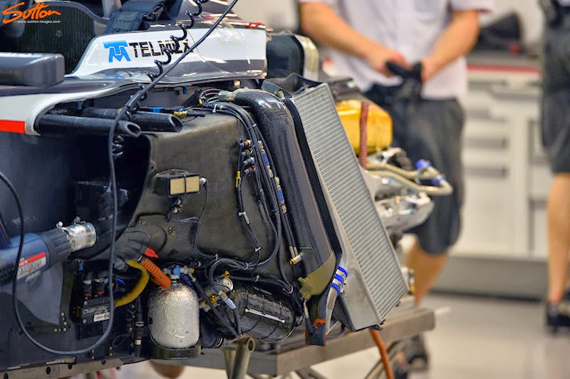
Component Installation
The core of the car runs along the
centreline of the car with the Chassis being the load bearing
structure that everything else bolts to. For 2014 most of the focus
will be placed on the new power units and understandably so, however
we must also play close attention to the ancillary components that
must be packaged alongside it.
The fuel cell will be reduced in size
for 2014 with 100kg fuel limit per race coming into effect, whereas
the current V8's use around 150kg's per race.
You'd also expect that the physical
dimensions of the V6 unit would be smaller than that of the current
V8's however due to the additional ancillary components of the Turbo
and ERS it will likely have a slighter larger footprint.
One of the biggest concerns for both
the engine manufacturers and teams will be cooling, with the
necessity to cool the charge air a probable concern. Supercharging
by means of an exhaust driven or mechanical turbine was outlawed by
Formula One in 1989 and since then we have seen the decline of engine
capacity from 3.5 litre V12's down to the outgoing 2.4 litre V8's we
waved off in Brazil this year. The FIA know that engine development
is crucial in terms of both it's environmental impact but also in
providing a worldwide rationale that things can be done more
efficiently. I won't go on too much in this article about the power
units directly, as I'll cover these more extensively in their own
article.
Suffice to say though that since their
use in Formula One 25 years ago the associated technology that
'Supercharging' brings to the table has increased exponentially.
Furthermore the designers grasp on internal aerodynamics has
increased rapidly too. The largest challenge facing the designers is
the scope needed for intercooling the turbocharged air. The initial
tentative diagram released by Renault showed a singular IC (obviously
not to scale) and the idea was enforced when Renault released further
pictures at the power units official launch.
Although Mercedes have released some
tentative images they are being more coy in terms of establishing
whether there is a need for an IC. Both manufacturer's show a
singular outlet on the Turbo which would suggest an asymmetric design
within the Sidepod to house the IC, however in terms of aerodynamics
this would have be a no-no with one Sidepod creating more internal
drag than the opposing side. So this suggests to me one of two
rationales, either the ICE doesn't require as much cooling and will
run with a singular radiator in one Sidepod with the Intercooler
placed in the other. Or the Intercoolers size parameters are small
enough for it to be housed underneath the exhaust outlet.
I would strongly suggest that the teams
will use a single pass intercooler too as their need to retain or
keep latent cooled air in the intercooler is limited.
The size and shaping of the
intercooler(s) and radiator(s) are of course essential when
considering the shape and design of the Sidepods. I suspect we shall
see teams edging back toward the type of sculpted design seen on the
RB6, with an aggressive undercut to the front of the Sidepod and a
tapered tail end clearing maximum area into the coke bottle region.
The efforts made by Sauber in the design and layout of the radiators and other components of the C32 may also stand them in good stead, whilst also highlighting the merits to other teams. Once the 2013 tyres were switched for 2012's construction it became apparent that although some had pointed to their radical Sidepods as an issue, they were not the root cause of their early season slump.
Airbox / Rollover hoop
Often overlooked but this area of the
car is one that each team has it's own unique take on, during the
last rule set we even saw teams trying on blade style, a trend
started by Mercedes (2010) and subsequently mimicked by Team Lotus
(now Caterham) and Force India (2011). The area is a battle between
aero and safety as the designers try to carve away as much space
around the structure as possible to aid in airflow. The structures
intent however is of course to prevent the drivers head from
impacting with the ground in the case of the car rolling over and so
safety is paramount. The airbox inlet therefore is the secondary
function of the area but nearly as important as it provides a much
needed breathing apparatus to the engine.

The last great turbo car the McLaren
MP4/4 and it's predecessors did away with the airbox inlet above the
drivers head and instead simply employed a roll hoop to protect the
driver. In the case of the MP4/4 it was powered by a twin turbo V6
and so the turbo's were packaged in either Sidepod. This of course
allowed the team to isolate the inlets outboard instead (Periscopes
atop of the Sidepods in this case). The new regulations stipulate
that the singular turbo must be placed along the centreline and so
this arrangement might not be pertinent as it would increase the
pipework length and complexity of the aero structures around the
Sidepod. I only bring up the matter from both it's historical
context and the fact the airbox does create a certain level of
blockage that impedes the rear wings performance. It's a necessary
evil of course as the engine cover also has to be designed with
dimensional criteria in mind and allowances are made to cater for the
airbox in the rear wings aerodynamic design.

More recently we have seen the 'Ears'
that were attached to the Lotus E20/21 airbox of which their primary
function was to facilitate DRD. The fact that the team bonded these
to the chassis however says more about the fact that the airflow
structure created at the airbox/roll hoop doesn't have a mass effect
on the Rear Wing. DRD was only run competitively once by Lotus on
Kimi Raikonnens car at Silverstone and so if the effects were
dramatic they would have removed the appendages.

The next part of this series will look at the changes around the changes to the rear of the car
I plan to get to as many of the 2014 car launches as is viable and also have an eye on making at least one of the tests. This however all costs money and so if you enjoy reading my blog and feel you can help to support financially I'd very much appreciate any donations you make (big or small). Donations can be made via the paypal button in the right hand side bar of the website.


Here's a question maybe you can answer. Can the turbo charger pull enough air that it would have an aero effect on the car?
ReplyDeleteThe simple answer is yes, quantifying these effects is difficult however especially as each design will differ and moreover we rarely see the internal pipework of the airbox.
DeleteThe complexity of the power unit far out weighs any research I have either conducted myself on my own turbo/supercharged track car and/or I have read in any research documentation. The unit is effectively being compound charged much like the 80's Group B Lancia Delta with the MGU-H playing the part of the Supercharger.
This means that the airbox will likely be designed with very specific targets as the air flowing toward the turbo will require a constant delivery / specific quantity of air per the engine speed. When the MGU-H is not in use it could lead to inlet pre swirl, If you know about turbo surge you'll also know that widening the compressor map would allow for a less peak operation of the turbo. The design of the inlet is one way in which to reduce surge and therefore turbo stall and so I'd suggest significant time has been spent on understanding the best way in which to maximise both ends of the scale. I mentioned the DRD pipework used by both Lotus and Mercedes as it would be altogether possible to utilise fluidic switches to your advantage when designing these conditions, however the regulations do stipulate that a maximum of 2 inlets can be used to feed the engine (Blade style roll hoops etc)
It's a massive area for development for the teams in my opinion and one which will only increase in significance for 2015. The reason being that variable length intake trumpets are only outlawed for 2014 at present (5.9.3 of technical regulations) and is the main reason I think Honda held off entering in 2014. Interestingly the new rules in the Sporting Regulations surrounding CFD usage also make development in this area a way of extrapolating performance that can then be fed back into the aero department:
Any simulation of flows contained within the engine cooling or lubrication systems, air, air/fuel mixtures, combustion process or products of combustion from a boundary commencing at the engine air intake duct, passing through the engine and finishing at the exit of the exhaust tailpipes will be classified as an Engine Simulation.
I'm quite sure this is something that I'll look into as the 2014 season progresses.
Thanks. Good response which adds to more questions about 2014 development
Delete