Open top menu
31 Jan 2014
no image


Formula One's portrayal on the silver screen has always been a difficult one to master but in the hands of Academy Award winner (Best Director - A Beautiful Mind - 2001) Ron Howard, the story of the 1976 World Championship battle between James Hunt and Niki Lauda was bought to life.

Formula One was still the pinnacle of Motorsport it is today back in 1976 but it could be argued with the lack of structure that came later in the 80's (when Bernie Ecclestone took over the commercial aspects) the sport was a little haphazard.  Having a copy of the 1976 (very rare) and albeit in German bar a few pages of diagrams and a couple pages of regulatory wording the regulations back then were flimsy at best.  Especially when we consider today's regulations are made up of both Sporting and Technical sections tallying 140 pages.  Innovation often came at the sacrifice of safety with everyone from team personnel to drivers accepting that their current race could be their last.  Meanwhile this attitude like the era in general often led to excess becoming a way of life.

Howard encapsulates the battle of triumph over adversity, the political infighting in the sport that often makes the action off the track as exciting as that on it and captures the relationship formed between the two opposing characters of Hunt and Lauda.  Played by Chris Hemsworth and Daniel Bruhl, both breath life into the flamboyant and introvert characters they respectively portray and the often obtuse lifestyles both led during a time that was fraught with safety issues.  The movie of course has to carefully highlight these factors with Lauda's crash being a pivotal part of the film and ultimately the lynchpin in not only the Championship, Lauda's determined recovery and the bond forged between the two mavericks before and after the horrific scenes at the Nurburgring.

Technically and contextually there are some omissions and/or embellishments in order to keep the flow and pace of the story in check but only the most technically anal or stalwart F1 fan could take umbridge with what is otherwise a fantastically crafted piece of cinema.

With Rush now available to rent on Sky Store for £3.49  they're also giving fans of the sport/movie the opportunity to win some fantastic prizes, all you need do to take part is rent the movie between now and 23rd February to be in with the chance of winning (terms and conditions apply, see link above for details):

1st prize - 2014 British Grand Prix tickets

  • 2 x seats in the VIP box at Silverstone on 4th, 5th and 6th July
  • A chance to go behind the scenes with Sky Sports F1
  • Three nights in a five star hotel and travel included

2nd prize - F1 Show tickets

  • 2 x studio audience tickets to F1 Show - at Sky Studios, London
  • One night in a four star hotel and travel included

3rd prize - Rush goody bag

  • McLaren team shirt signed by Jenson Button
  • Rush poster signed by the movie stars and director
  • Official McLaren team membership - for one year
  • James Hunt biography
My original review of the movie can be read here: http://somersf1.blogspot.co.uk/2013/09/rush-movie-review.html
Read more
F1 in 2014 - Explaining ERS energy flows and speculating over the use of Off Throttle Turbo Blowing (Gating or OTTB)

Formula One embraces a new powerunit for the 2014 season taking the recovery and usage of electrical energy to a whole new level.  At the core of the power unit lies a smaller capacity 1.6 V6 Engine of which we find a singular turbo, all sounds fairly mundane eh?

Well here's where it becomes a little more complex, married to the turbo shaft we find a MGU-H (Motor Generator Unit - Heat) this is fancy terminology for an electrical motor.  Furthermore attached to the crankshaft (via a gearing arrangement) we find a MGU-K (Motor Generator Unit - Kinetic) which is essentially a beefed up version of the KERS electric motor used by the teams in one form or another since 2009 (excluding 2010).

Several complexities arise when we establish that these 2 electrical motors can be utilised to recover energy and dispense it and even more so when we consider their power input/output relationship.


As always the manufacturers/teams/F1/FIA have been coy in explaining the usage of power and we tend only to see power figures etc displayed in a linear format.  The problem with this is that we now have to see KERS as analog and ERS as digital, with the former providing ex BHP for a set time that the driver pressed a button or triggered a paddle on the steering wheel.  ERS will be intrinsically linked and mapped to the position of the torque/throttle/accelerator pedal meaning that the way in which power is harnessed can be altered in a 3 dimensional context.

Based on KERS being able to dispense 80bhp (60kw) for 6.33 seconds (400kj) it has widely been written that ERS via the MGU-K will propel the car for 33.33 seconds (4MJ of which 2MJ is harvested under braking from the MGU-K and the rest must be made up by the MGU-H) with an additional 160bhp (120kw) now of course this is correct if we use the same linear thinking that was applied to KERS.  We must however think differently as unlike KERS the new system can be mapped alongside the ICE to produce power at different gradients.  So for arguments sake lets imagine the throttle pedal has 100mm of movement from no input through until WOT.  In order to afford the driver more traction the first 25mm could provide no additional power output from the MGU-K with the next 75mm providing a gradual curve of additional power all the way up until the full 160bhp.  There are of course a plethora of ways this can be mapped and will likely involve a great deal of setup prior to each GP on the simulator and more work at the track during Free Practice sessions.

As you're now seeing the MGU-K's energy release as a 3D map you'll also realise that the time component of 33.33 seconds used above is junk and will likely result in much more energy available to the driver throughout a lap. Hopefully this will allay any fears you had about the drivers only having the 600bhp the ICE produces when not supplemented by the MGU-K.

As I've only covered the MGU-K thus far in the ERS lets have a look at the MGU-H which takes care of regulating the Turbo's speed. 

One of the issues with turbocharged engines is lag, the bigger the turbo, the more lag you tend to get.  Motorsport has been intrinsically involved in the development of technology surrounding turbochargers in the past, with VGT (Variable Geometry Turbo) and anti lag just a few methods employed to increase power or efficiency.  These methods are not available to the engine manufacturers for the new power units but the MGU-H looks to profit from the motor generator unit in the same way (spooling up the turbo for instantaneous power).

Each of the manufacturers (Ferrari, Renault and Mercedes) will have undoubtedly taken different paths in terms of how to mount the MGUH to the Turbo but invariably that just takes into account how they want to utilise it and package it.

The MGU-Hs job is to essentially keep the turbo spooled up for instantaneous boost when the driver returns to the throttle.

As we can see from the energy flow diagram from above the MGUH is governed by several pathways. An unlimited amount of Energy can be recovered/stored whilst the same can be said for usage from the Energy Store (ES). The one constant however that dictates how and when the energy can be used is that ES cannot exceed 4MJ per lap.

The other option however is that energy passes directly between the MGU-H and MGU-K missing out the middle man (ES).  Of course the best way to do this is when the driver is off throttle, recovering energy via the MGU-K under braking and out of the low traction phase pass this to the MGU-H to keep the Turbo spooled. On the flip side the MGUH will act like a mechanical wastegate, harvesting energy from the Turbo as the boost climbs at an adverse rate and feed it directly to the MGUK to facilitate more power.

This process will require intricate mapping by the team/manufacturers engineers as with the throttle closed and boost being created it could lead to "Surge".  This is an undesired effect as it will undoubtedly shorten the lifespan of the component and increase the heat within the unit.


However how about if we utilise a wastegate? A wastegate is the manual method of bleeding off excess turbo pressure and is set to a prescribed pressure, at which point the wastgate opens and in the case of the 2014 (onward) engines would expel the unwanted boost out of the exhaust (again a precise and complex process due to the interaction of exhaust gases post turbo).

The Speculation part of the article: Will we see/hear Off Throttle Turbo Blowing - OTTB

Are wastegates even allowed? I refer you to the 
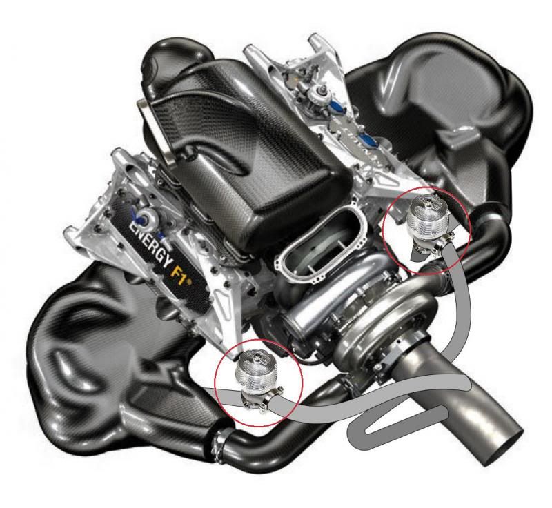
Renault Sport F1 page, as the manufacturer who has been most candid about their 2014 PU, they openly discuss the complexities of using a wastegate within the system.  Due to the V'd ICE configuration and the way Renault talk about packaging it's safe to assume that an external wastegate will be the weapon of choice, however I'd also suggest this could become plural due to the way the gasses enter the Turbo.

Above: In this image I've added twin wastegates (circled in red) and some of the main associated pipework that allows the exhaust gasses to miss the turbocharger.


Brilliant, haven't we chanced upon the newest form of exhaust blown diffuser (EBD)?

Not quite, EBD's used in the last rule set worked on the principle of sealing the Diffusers outer edges. As we know the exhaust exit has been specifically placed along the centreline of the car in a tip up format by the FIA to try and prevent EBDs being proliferated.  Furthermore the height at which the exit must be placed is set at between 350 and 550mm from the reference plane meaning its interaction with the Diffuser's edge is made more torturous.  Armed with this information we can see that it will be somewhat difficult to utilse off throttle blowing in the same manner but that's not to say it cannot be used in a different way....

The loss of the Beam Wing which resided between the rear wing in previous seasons in order to mount the wing to the crash structure, also created an aero structure which allowed the Diffuser and Rear Wing to interact (or talk to one another as such).  With all three airflow structures working in unison the teams were able to maximise the level of downforce created whilst maintaining a lower level of drag.

Above: In an effort to show the interacting flow structures mentioned in the paragraph above I've drawn on the basic flow structure (Upwash) at work.

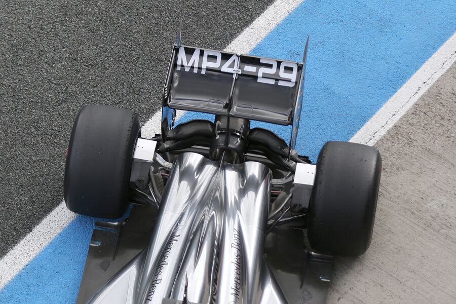
Not wanting to lose this effect McLaren have taken the option of shaping their Wishbones into a profile that replicates the Beam Wing and have begun testing it in Jerez.  However with the exhaust placed centrally McLaren and the rest of the teams will try to re-enact this airflow using the exhaust and the surrounding components.

Above: Without the Beam Wing to interact with the upwash the connection between the aero structures is weakened resulting in a breakdown of downforce/efficiency over the 2014 cars predecessors.  The teams are looking to minimise these losses by introducing intricate Endplate designs, complex Y100 Winglets (Monkey Seats) and also use the mounting pylons for potential aero gains.

However lets think about when these flow structures are required the most: Off Throttle.  As the driver comes off the throttle and enters a corner he wants maximum downforce in order to attack the corner, if the teams/PU manufacturers found a way in order to keep the airflow interacting more downforce would become available.   A plausible way of doing this is to use the MGU-K in order to slow the vehicle (harvesting) whilst sending the power directly to the MGU-H to keep the turbo spooled, as the pressure is raised in the TC by the faux spinning of the compressor by the MGU-H there needs to be a pressure relief as the throttle is closed and can't accept the rising boost levels.  The Wastegate(s) cut in and dispatch of the the airflow out of the exhaust, placement and pipework to and from the wastegates would be essential not only because there is performance to be gained under normal operation of a wastegate in this manner, but by placing the wastegate exhausts on the pheriphery of the main exhaust in the right position you can also make the airflow move helically, energizing it's flow.  I believe this may have been a reason why the FIA changed the regulations late on to stipulate a singular exhaust exit as it would have been much easier to gain an aero advantage from a smaller singular wastegate exhaust mounted correctly than what I've proposed here.

Like the off throttle blowing we saw in 2010/11 the drivers would have little to do in regard to controlling this effect as the systems at play would be complexly mapped before they even climb aboard.

During the last use of off throttle blowing we also talked about the use of cylinder deactivation by the teams to continue pumping airflow through the engine (for aerodynamic performance) and not only that but retain some throttle rather than the driver having to ease all the way off.  Cylinder Deactivation will still play a large role in the V6 engines with an increase in fuel efficiency when at low throttle input, whilst the move by F1 to direct injection means the fuel injection stream is more precise and optimizes flame propagation.  For those uninitiated in the phrase cylinder deactivation this is the practice of shutting down a number of cylinders in order that the remaining cylinders operate at peak efficiency, saving fuel and lessening the transition between full and open throttle.  With fuel efficiency at such a premium due to the 100kg weight limit imposed for the race, the use of tactics like cylinder deactivation will become common place.  If we also refer back to the insinuations I have made about gaining an aero advantage from the Turbo Wastegate(s), cylinder deactivation can also be used to manipulate this flow.

The whole scenario is fraught with complications owing to the complexity of all the systems at hand and so I look forward to seeing how all of this new technology is handled by the teams and PU manufacturers.  Many have also complained in the past that these V6 engines will sound terrible when compared to the outgoing V8's, my retort has always been the same, "They will sound like nothing else, intrinsically Formula One" and with that I leave you with the following video taken at the first test in Jerez.  Make your own mind up but personally I think they sound fantastic, an amalgamation of V6 exhaust, Turbo and electrical energy.


Read more
30 Jan 2014
29 Jan 2014
McLaren MP4-29 Upgrade - Wishbone Wings

The season might seem a long way off for some people but with all but the Lotus and Marussia having physically broken cover (at the time of writing as the Marussia will come from under the covers shortly), McLaren have already pulled the wraps off what some may consider to be a silver bullet.


At first glance you'd be mistaken for thinking that McLaren still have a Beam Wing running horizontally across the Rear Wing structure but at second glance it's clear to see that there are 2 structures in front of the Rear Wing (Highlighted in Yellow).  Furthermore from this image alone you cannot infer depth and so it looks like the suspensions Wishbones (rear section of the upper and lower arms) have been flipped vertically.


(Click on the Images to them in full resolution)

What we can see from the top down view is that the team have simply designed a much boxier version of their Wishbones, getting thinner at the point around the Endplate.

The regulations surrounding Suspension elements that these boxier 'Wishbone Wings' circumnavigate are:
10.3.1 With the exception of minimal local changes of section for the passage of hydraulic brake lines, electrical wiring and wheel tethers or the attachment of flexures, rod ends and spherical bearings, the cross-sections of each member of every suspension component, when taken normal to a straight line between the inner and outer attachment points,must :
a) Intersect the straight line between the inner and outer attachment points.
b) Have a major axis no greater than 100mm.
c) Have an aspect ratio no greater than 3.5:1.
d) Have no dimension which exceeds 100mm.
The major axis will be defined as the largest axis of symmetry of any such cross-section. The length of the intersection of this axis with the cross-section must not be less than 95% of the maximum dimension of the section.

10.3.3 No major axis of a cross section of a suspension member, when assessed in accordance with Article 10.3.1, may subtend an angle greater than 5° to the reference plane when projected onto, and normal to, a vertical plane on the car centre line with the car set to the nominal design ride height.

If we now look back at the launch image I used to show the rear suspension we can see that the Wishbones are shaped into 2 sections,  a shorter chord at the inner section and wider profile outbound of that.  Furthermore as part of the crash structure we also find the Wishbones to be mounted within what look like aero shaped fins.  If you now re-check the images above you'll see I have marked two sections in Red.  These sections are further additions run on the car with the Wishbone Wings, allowing airflow to bleed out the central portion of the car and interact with the exhaust plume.


As we can see on the left the Wishbone Wings aren't simply flat fronted boxes but due to the aspect ratio and 5 degree rules, they can't simply be made into upturned foils/wings in full replication of the Beam Wing.

The other thing to consider here is that the wishbones are moving entities and so the gap between both elements will change based on the attitude of the car.

This is where it gets tricky as both the airspeed will change under braking and acceleration as does the gap between the profiles meaning airflow attachment could become an issue especially with sudden changes of direction.
A brilliant overhead shout of the car

I realise that Gary Anderson has already weighed in on the topic stating that if this does turn out to be a silver bullet it could be difficult for some of the other teams to implement.  I'd have to agree to some extent but if it is seen as worthwhile they will all try to integrate it, however it would undoubtedly effect the teams with enclosed driveshafts more (aka Red Bull, Mercedes & Toro Rosso) due to the way in which the geometry of their suspension etc is designed.


I look forward to seeing this development evolve as it's clearly only in the beta stages and will update the article with more images etc when they become available.

EDIT 13/01/14

As traffic is filtering back to this article I'll point out a few extra things about the Wishbone Wings that perhaps weren't present in this original article:

I looked at the Wishbone Wings in more concise detail here: 'Wishbone Wings' analysed and explained furthermore I showed a tech colleague this picture over on Twitter this morning alluding to the fact that McLaren like Toro Rosso and Williams are also utilising a structural and aerodynamic lower wing element which will further enhance the airflow structures and the way they all link together.  (See also: Bite Size Tech: McLaren MP4-29 Rear Wing Endplates that create 'upwash')


Related articles
Enhanced by Zemanta
Read more
Caterham CT05 Launch Analysis

Since their arrival in 2010 the team have gone through several guises. Under the watchful eye of their owner Tony Fernandes the team were the 'best of the rest' for the first few years and 2013 can really be seen as a transitional year for the Leafield based team.  Continuing their partnerships with Renault (PowerUnits) and Red Bull Technology (Powertrain) can be seen as shrewd move allowing the team more time to concentrate on areas that can bring later performance, chassis design and integration.  Having continued to invest in infrastructure the teams move to Leafield last year was done to coincide with the change in technical regulations and to base them closer to the Wind Tunnel they use (One of Williams tunnels in Grove).

An all new driver lineup of Kamui Kobayshi and Marcus Ericsson aligns experience with youthful exuberance (although Kamui has the exuberance bit in spades too LOL).

Front Wing

The CT-05's Front wing is a clear evolution of it's predecessors but clearly makes tremedous effort to pick up and manipulate the airflow toward the outside of the front tyre.  An inbound Vertical Strake (Similar to the one on the Lotus E21's Front Wing) with thick profiles has a perforated section designed to move flow outbound.  Whilst outboard of this we find the Cascade in it's usual position but again we
see the appendage has been orientated in order to turn flow outward.  This is aided by the vertical vane placed just off centre in the Cascade.

The Wing's Endplates have also been treated to an opening and splaying with the Endplate now split into 2 sections.

Nose

Mirror, mirror on the wall who is the fairest of them all? Certainly not this one.  Caterham have taken a rather extreme approach to the nose regulations, hoping that will increase performance downstream.

What it does is utilise a large section of Vanity Panel (the rearward wedge shape) as we saw when Caterham conducted their crash test (Image below shows the wedge shaped Vanity Panel being flung off the car in the frontal impact test.  Meanwhile the frontal finger section of the nose is also wedged shaped in order to enclose the central section of the nose as it meets with the upper section of the nose

This means that the actual crash structure is made up by another element that sits within the faux panel arrangement.  When I initially looked at the Nose regulations I realised there were many ways to skin the cat and so set about drawing out a few of these ideas.  The one used by Caterham is similar to the design I drew out below save the use of the Vanity Panel over the rearward section in order to maximise the airflow underneath the chassis.

The crooks of any of the designs seen on the cars centres around what can be done with the internal crash structure (lower picture) and as long as it meets with the central point regulations at the tip a vanity panel could and will be used to make up the aero benefits needed by the team elsewhere.  The solution employed by Caterham is very aggressive and although it won't win any beauty awards you have to congratulate the team on their endeavors to push the regulations.

The only other question remains is it the best solution?  That is something that will need to be assessed on track but the abrubt shaping of the wedge (although it takes the regs to around their limits) is not always the most effiecient way of skinning the cat.  For example whilst the likes of Ferrari, Mercedes, McLaren etc pushed the maximum height rules over the last couple of seasons Red Bull did not and were probably around 100mm off the maximum height.

Caterham are however leveraging their aggressive intentions with other design considerations with the team utilising Pull Rod Front Suspension for the first
time something that Ferrari have been doing for 3 years now.  Pull Rod isn't inherently any different from it's Push Rod counterpart in mechanical terms but if implemented correctly can give an aerodynamic advantage.  Furthermore the team have implemented a tray underneath the wedge section similar to the 'Snowplough' utilsed by McLaren in 2010 (Coinciding with John Iley's time at the Woking based squad).  The Snowplough takes the place of the more vertical Turning Vanes operating in the same way but also taking into consideration the horizontal flow.


Sidepod

The Sidepod inlet on the CT05 appears to be the largest we have seen thus far and although this will be good in terms of cooling, that drag penalty won't be a side effect the team will relish.  Opting to continue with their twin Sidepod Airflow Conditioner that adorned it's predecessor the airflow around and over the Sidepod is framed.  Whilst along the side of the Cockpit we find an elongated triangular fin designed to vorticise the airflow combined with another curved fin fitted behind it similar to that run on the Red Bull RB9.


As we can see from the side profile due to the bigger inlet the undercut is not so pronounced on the CT-05 and could inhibit the flow around to the rear of the car.  Although a collection of aerodynamic enhancement proliferate the leading edge of the floor around the base of the Flow Conditioner one of which is again a nod to Lotus / Red Bull (Detached Floor Scroll)

The Bagreboard is a carry over from last year and will likely change over the coming weeks to enhance the region.

The rear of the Sidepod is treated to a decent undercut with a high waisted cooling exit taking advantage of the onward flow over the suspensions wishbones.  The floor ahead of the rear wheel looks fairly straight forward at present and is another area where the team may be able to find gains.


Rear End

Having decided to mount the Rear Wing on 2 centralised pylons the team take advantage of that rigidity with tyre wake slots that run almost the entire leading edge of the Endplates.  Housed within the structure of the pylons we find a Winglet at the full width of 200mm above the exhaust outlet, placed to maximise the upwash of the exhaust.  Work has been carried out to the Diffuser with the team opting to use footplates at either end of it this time around.  Whilst the team also seem to have spent some time designing their Rear Brake ducts to maximize efficiency.  What is most interesting is that although the team purchase their Gearbox from Red Bull Technology they have opted not to run the halfshafts enclosed within the wisbones like Red Bull and Toro Rosso have.

Of course this is an early look at the car and I'll update the page as and when more images / information becomes available.  Please feel free to ask any questions relating to the car and it's design in the comments section below and I'll try to get back to you in due course.


Enhanced by Zemanta
Read more
Explaining the W05's Nose in terms of construction

I've a few people say to me they cannot understand how I'm able to say with any certainty that the WO5's nose is made up with a crash structure that forms only one side of the 'Teeth' whilst the other is a Vanity Panel.  Therefore I'll do my best to explain the situation.


When we look at the WO5's nose we note it bears resemblance to the Ferrari F14T presented thus far, however on the Ferrari the gap between the Mainplane and centre section of the nose (tip) remains at the specified 185mm from the reference plane (Ie 60mm above the Mainplane).  The faux nose tip of the WO5 is actually 65mm higher at 250mm high.  How do I know this you're going to say...


Having already seen the Lotus nose and uproar it caused I mentioned at the time that I had floated such an idea several weeks before.  My idea (above) was a little aggressive and perhaps didn't take into account all of the dimensional constraints surrounding the curvature of the nose in the bodywork regulations.  However what it did do is highlight what sort of scenario was available.

The Mercedes nose follows a similar premise and so I've drawn onto the image below to try and explain the situation.


You have to consider 3 separate constructs, the connecting pylons are drawn in yellow and have a maximum width of 25mm and could extend up the side of the inner 'teeth' in order to add rigidity to the wing (although this will of course make the space between the pylons narrower.  The periphery of the nose is made up by the actual crash structure (drawn in red) meeting with the following key regulations:

15.4.3 An impact absorbing structure must be fitted in front of the survival cell. This structure need not be an integral part of the survival cell but must be solidly attached to it.
No part of this structure may lie more than 525mm above the reference plane.
It must have a single external cross section, in horizontal projection, of more than 9000mm² at a point 50mm behind its forward-most point. Furthermore :
a) No part of this cross-section may lie more than 250mm or less than 135mm above the reference plane.
b) The centre of area of this section must be no more than 185mm above the reference plane and no less than 750mm forward of the front wheel centre line.


The section that talks about 9000mm2 at 50mm behind it's forward most point means you must project that area at no less than 135mm and no more than 250mm above the reference plane.

One of the 'teeth' to allow this to be legal must be placed at 50.01mm (at least) behind the other (as we saw in the Lotus mock up) I have therefore marked in Green what is most likely made up as a Vanity Panel to create the symmetry and make the design legal.


Read more
28 Jan 2014
Infiniti Red Bull Racing RB10 Launch Analysis

The quadruple World Champions have it all to do again and never a team to rest on its laurels I see no reason why they won't be mixing it at the front once more.  Their meteoric rise was of course by no means a fluke and took huge investment, the forming of great technical partnerships, an army of staff dedicated to the cause, the taking of calculated risks and of course huge ambition.  Often seen as just the 'party team' in the early days they entered the sport at just the right time but bore the tedium of 4 years of poor results as they tried to catch up with the more structured elite teams.  The regulation changes of 2009 changed the face of the sport in a way that was conducive to the direction they had taken and fitted perfectly with Newey's aero driven mindset.  Of course without other key members like Rob Marshall and Peter Prodromou and a fantastic array of staff under their lead things may have been different.  The RB10 then has a challenge on its hands as all the other teams have their sights firmly set on knocking the team down a peg or three but rest assured the boys and girls at Red Bull won't go down without a fight.

Front Wing

The first striking point about the Front Wing is the change in approach at the Endplate, featuring a curving slot as the base of it will allow airflow to pass from both sides of the Endplates but airflow will predominantly feed outbound around the front tyre.  The front lower edge of the Endplate also features a curved section which again will influence the airflow aft of it.  From the angles available at present it's unclear if it's a 6 or 7 tier wing but I'd hazard a guess at the latter.


Nose

The RB10 is another to feature the 'Finger' nose but approaches it several different ways to the ones we have seen so far.
The tip has been focused into a flat top keeping a smooth transition line along the top surface of the nose.  This therefore means to meet the regulations that the front end of the nose is fairly tall.  Red Bull have attacked this with verve however and turned the frontal section into a bow shape which reclines
backwards toward the outstretched nosecone.  The lower shape of the nose also tapers from the tip clearing as much room between it and the Mainplane below as possible.  The nose tip is populated by a cleverly designed inlet that maximises both the opportunity for it to be used as driver cooling but also mitigate any aero issues by placing just an open inlet in that position. The airflow otherwise confronted there onwards by an expanse of bodywork is treated to a 'Pelican' underbelly (outlined in Green) that facilitates the speeding of the airflow rearward and towards the central 'S' Duct. 

It's a similar concept that adorned the RB9 with an inlet placed under the nose and another jutting slightly out of the top surface (lower image) of the nose before it meets with the Bulkhead.  The under nose inlet however is still a little mysterious as it is split into 3 channels, the inner one feeds the 'S' Duct (outlined in Red) and I'll speculate that the outer two ducts (outlined in Yellow) simply feed along the periphery of the Turning Vanes in an enclosed tunnel to assist their flow.  The upper outlet of the S Duct aids airflow over the top of the chassis with the steep nose incline causing separation as the chassis flattens back out (Think about how the Coanda exhaust worked ;) a tangential jet of air helps with attachment and is attracted to a nearby surface. )


Sidepod

A relatively small inlet means the RB10 also features a large undercut for which the airflow can make it's way to the rear of the car.  Sidepod Airflow Conditioners, Slotted Bargeboards, Detached leading edge Floor Scroll and Horizontal Cockpit Vortex Generators are all carry over from the RB9 at present but may change before the season gets under way.


The rear of the Sidepod is taken care of with a high waisted cooling outlet that enables the airflow room to flow underneath to the coke bottle.  Ahead of the rear wheel the floor has several tyre squirt slots which also twisted to increase their effect.  Inbound of this the floor also features a singular Vertical Floor Strake (reduction from the RB9 which used two Strakes)


Airbox / Roll Hoop

If it isn't broke don't fix it seems to be the the moto at Red Bull as the intrinsic design layout of the Airbox is very similar to it's predecessor.  Unlike Toro Rosso the team haven't felt the need to add a scoop underneath the main airbox and instead retain the undercut for cleaner airflow.


Rear Wing

Using a mounting pylon affixed between the upper section of the Engine Cover and wings Mainplane for rigidity I'd have expected a rather aggressive Endplate design.  Aggressive it certainly isn't, moreover it's devoid of many of the regular design considerations that are usually seen by the leading teams.  One would have to assume that many of the items on the RB10 are simply placeholders and instead the team are simply working on getting the bugs out of the car before really looking at performance.


Compared with it's sibling (STR9) the rear of the car seems incredibly rudimentary, devoid of lots of the aero tricks that even the STR9 features.  The RB10 retains it's enclosed halfshaft lower wishbone arrangement which cleans up the airflow over the floor.

I will of course update the article as soon as the team decide to pop some actual parts on the car.
Read more
Mercedes W05 breaks cover then breaks its front wing

The first day of 2014 testing came to an abrupt end for Mercedes as the car carrered off the circuit at the hands of Lewis Hamilton in turn 1, after completing several laps of Jerez.

The failure was reminiscent of what happened to Hamilton at the circuit last season. The cause of the failure has yet to be firmly ascertained but from looking at the images at the circuit it seems the connecting pylons failed, turning the car into an uncontrollable sled as the front wing lodged itself under the front wheels.


The connecting pylons that failed are the much narrower sections at the base of the connection between the nose and wing. The pylons are only permitted to be 25mm wide whereas the wider section above this is Mercedes way of circumnavigating the new nose regs. One of those wider sections is actually 50mm longer than the other and a vanity panel replicates the symmetry on the other side. Full analysis of the car/nose here: http://somersf1.blogspot.co.uk/2014/01/mercedes-amg-wo5-technical-launch.html?m=1

With one or both of the thinner pylons having likely failed under braking the nose will have twisted as it ripped the vanity panel away from the crash structure and folded the whole structure under the car.


It would appear that the front of the front impact structure sheared off (one of the teeth) which is good in some ways but just goes to show the mockery the teams make of the rules.

Read more
Mercedes AMG W05 Technical Launch Analysis

No shadow of a doubt, Mercedes were the most improved team of 2013.  The Silver Arrows upturn in form came as a surprise to some of the paddock as they often topped the time sheets come Saturday afternoon.  It's been quite a journey for the Brackley based squad over the last few years. Following on from the Championship winning BGP001 was always going to be a difficult task, made more difficult by the cuts made to survive in 09 and restructuring that followed with the sale to Mercedes.

That gestation period comes full circle once more with a new set of regulations, key personnel on board along with investment in infrastructure likely to pay dividends. It will be interesting to see how the dynamic changes with Ross Brawn stepping aside and Paddy Lowe taking on the technical aspects of Team Principle, whilst Toto Wolff looks after the commercial aspects, all the time under the scrutiny of none executive chairman and F1 legend Niki Lauda.

The teams timing and confidence shown by Stuttgart in order to facilitate the changes may prove crucial, with perhaps the biggest and most pivotal change coming toward the middle of 2012.  The decision to invest heavily in the team not only inspired Lewis Hamilton to join the team but paved the way for new tooling and modifications to their wind tunnel to take it and production to 60% rather than 50%.

2013 was just the precipice in terms of the results that can be achieved by these changes. With the Coanda exhaust fully implemented in the WO4 and providing a better platform than the job done to place it on the WO3 mid season it provided their fans with some solace. The team also made big strides forwards with their Front Wing design providing much needed new impetus on a design that had been being used as an evolutionary platform since the 09 campaign.  Other key areas of the car saw decent development and indicates the team are heading in the right direction for 2014.

Having already released several teaser images ahead of the actual launch some of the key design features had been seen before the unveil.


Front Wing


The W05's Front Wing is a refined version of it's predecessor taking into account the loss in overall width (150mm or 75mm either side) the Main Cascade has been treated to an additional Vertical Strake to aid in turning the airflow around the upper outer quadrant of the tyre's shoulder.  In the outer portion of the now split Cascade we see the team have once again installed an IR camera to assess the thermal properties of the front tyre.  Added to the
larger Cascade we find a smaller one very much (aesthetically) like the one used on the McLaren. The Endplate features a slotted horizontal vane similar to curved version Lotus ran at one race last season.  This vane encourages a high pressure gradient against it's lower side to force airflow out of the slot, this undoubtedly helps the region turn airflow outbound.

Nose

Mercedes have taken a similar route to Ferrari in their adoption of a high chassis and step from the nose with a graduated rearward/inverted slope to the main section of the nose.  However in order to gain more space between the Mainplane and Nose tip they have used the work around in the rules similar to that of Lotus who presented their Sabretooth before them.  The nose has been made with 2 hanging pylons in order to meet the 185mm nose tip
height and 9000mm2 cross section at 50mm behind
the tip regulations, with one side longer than the other but the opposing shorter side flanked by a Vanity Panel.  Slighty rearward of the noses hanging wider pylons we find the much narrower connecting pylons which arc backward to maximise space under the nose.  Like Ferrari the team have utilised the mounting of the FOM cameras to glean a small aerodynamic advantage, arc'ing bodywork from the nose over to the mounting points.  This adoption reminds me of the 'Elephant Ears' the team used back in the Honda days.

Sidepods

At the front of the Sidepod the inlet seems relatively small compared to the McLaren running the same Powerunit, whilst the team have chosen to run the same triangular cockpit strake ahead of the pod as last year.  On top of the Sidepod we find two Vortex Generators with opposing designs looking to change the airflow in different ways.  The Sidepod Airflow Conditioner is doglegged like last years design in order accentuate the Sidepods inlet profile and allow maximum airflow around toward the coke bottle.  Cooling from the Sidepod is taken care of with an outlet ahead and inline with the Suspension pickup allowing space underneath for the airflow to cut around into the coke bottle..

Roll Hoop

The team have worked hard on maximising the undercut which allows a cleaner flow of air to the rest of the car, mounting the construction spars in a lent backward orientation encourages the airflow to pass over the engine cover aft of it.


Engine Cover

Featuring a Shark Fin to meet with the dimensional regulations we also find a pair of outlets at the base of the fin which undoubtedly aid in the targeting of the exhaust gases exiting behind it.


Rear Wing

Mounting the rear wing for all the teams this year has been a decision based process of strength over aero, the loss of the Beam Wing has meant that teams either make their Endplates more rigid or run with centralised mounting pylons.  Mercedes have decided to go with the latter option and likely because they have decided to utilise serrations in the Endplates lower rear section. This is a departure for the team who have failed to follow the lead of other teams over the last few seasons in using Trailing Endplate Strakes.  The team have retained the leading edge tyre wake slots they used on the W04 but have moved them much closer to the leading edge and run them much lower to the bottom of the Endplate.  The catalyst for the move coming from the serrated/fanned trailing sections of the Endplate which will of course aid in creating upwash, something that will be sorely lost along with the Beam Wing.

Diffuser

The Diffuser seems to have a very thin U section in the central portion of the Diffuser which collates airflow from the upper surface of the floor ahead of it and uses it to enhance the Diffuser (Dare I say it very much akin to the DDD approach, but obviously no holes within the surface of the floor).

Exhaust

Initially it seems to be a fairly rudimentary approach when consider some of the other more complex looking designs around that area but the team could have other components in the pipeline with this less complex arrangement used for initial testing.

Floor Treatement

Ahead of the rear wheel we can see that Mercedes have retained the tyre squirt slot that the W04 ran but the Vertical Strake inbound of it has been straightened with it's predecessor having been arched.


Of course this an early look at the car and so any additional images/info that becomes available will be posted ASAP

Read more

Total Pageviews