
.png)
 By
By  Tuesday, February 03, 2015


Ferrari SF15-T - A kiel probe array is placed behind the front tyre to measure the wake, correlating the information the team produced the car with.


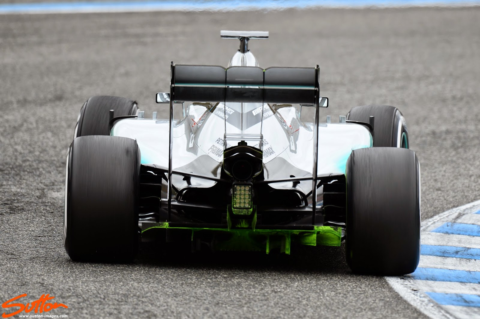
Williams FW37 rear end detail

Toro Rosso STR10 rear end detail, note the area had previously had flo-viz applied


Sauber C34 sparking as the titanium skids impact with the track


Nice rear detail shot of the SF15-T

Note the hollow blown front axle on the SF15-T, air captured by the front brake duct which has inlets within that send airflow into different regions such as the caliper, disk, one of these on the SF15-T sends airflow to the hollow axle. The airflow dispatched by the axle helps with conditioning the flow around the front tyre, taking some of the burden off the front wing.

This shows McLaren's new wheel design and like the Ferrari above the hollow blown axle being employed by the team

McLaren, able to put in a little more mileage in Jerez today tried out the other variant of rear wing endplate the team showed at the launch


Toro Rosso STR10 with flo-viz applied, I don't know the story on the attached black bag yet by the way, but I'd assume it wasn't supposed to be attached

SF15-T with flo-viz applied to the nose and chassis

Toro Rosso STR10 rear end detail


Sauber C34 - Another shot of the rear end of the C34

Red Bull RB11 - Flo-viz applied to the side of the chassis to correlate what was being seen in CFD/Wind Tunnel


Williams FW37 splitter covered with flo-viz to check the flow in the region

Nice forward shot of the FW37


Williams FW37 - the team have added vortex generators to the leading edge of the sidepod


 The Lotus E23 airbox which as you can see sports several different outlets


Excellent article
ReplyDeleteMega!
ReplyDeleteAh, my favourite time of the F1 year. New cars and new driver lineups. Some pretty amazing aero wizardry going on at the rear of the cars, especially on the C34. Lots of ways of cat skinning going on with the others too. Lots of things going on around the E23 airbox. Reminiscent of the DDRS year. Mark's images are stellar - need eyes with more megapixels too. Wish I'd invented Flow-Viz.....and pyrometric strips. >1.8 mill page views. Award winning!
ReplyDeleteVery interesting to see how different the Lotus airbox & roll hoop structure is compared to the others.
ReplyDeleteBit puzzled though.
DeleteThe text which goes with the pic,talks about the different outlets!
That surely should have been air intakes, or am I mistaken?
Wim van de Kimmenade